STEP to DXF
Create a 2D silhouette by projecting the model onto XY, XZ or YZ. Projected triangles are merged so internal triangle edges disappear. Openings visible through the whole model remain holes in the outline.
Your model goes here.
Choose your file or try the original sample below. No installation or sign-up.
01 / HOW IT WORKS
Open, inspect, then use your result.
- 01
Open your file
Choose, drop or paste your STEP file. All three input methods use the same local checks.
- 02
Look from every angle
Choose the drawing parameters and apply them. Inspect the resulting outlines or solid before downloading.
- 03
Download the converted file
After conversion, download DXF. Open the result in your destination software and check the units before use.
02 / TRY IT YOURSELF
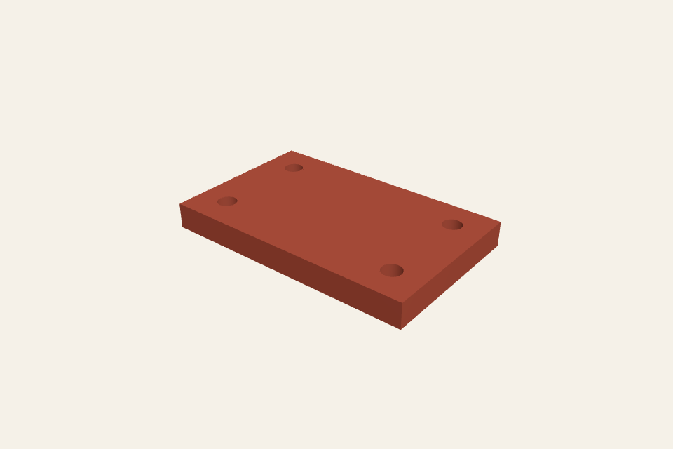
Inspect the sample in the workspace
Use the sample to inspect closed outlines and holes, then apply your own output size or projection plane.
Original public sample. Your uploads are never added to this gallery.
03 / FORMAT & USE
STEP to DXF
Create a 2D silhouette by projecting the model onto XY, XZ or YZ. Projected triangles are merged so internal triangle edges disappear. Openings visible through the whole model remain holes in the outline.
What this viewer supports
Orthographic silhouette only, not hidden-line engineering drawings, sections or bend patterns. STEP is tessellated before projection. Curved edges become polylines. The projection accepts up to 20,000 non-degenerate projected triangles. Projection accepts up to 20,000 non-degenerate projected triangles and rounds coordinates to 0.000001 mm before joining outlines.
STEP and STP solid models up to 32 MiB and 2,000 solids. The converted geometry must also fit a 16 MiB internal limit, so file size alone does not guarantee a model will open. Complex models may exceed the time or memory budget.
04 / QUESTIONS
Know your input. Understand your output.
Why are some holes missing from the projection?
A silhouette describes the area covered by the model from the selected direction. Blind holes or openings blocked by other surfaces do not cut through that area. Choose another plane or use a dedicated engineering drawing workflow.
Do I need an account or credits?
No. These tools are free and run in your browser. No account, subscription or credits are required.
Is my model uploaded?
No. Your selected file is read and processed in this browser. The page downloads its CAD engine and public samples, but does not upload your model. Refreshing or leaving the page clears the current file from the tool.
How are units and orientation handled?
The overall bounds come from the imported solid geometry and are shown in millimetres. They are not point-to-point measurements or drawing tolerances. If the declared units are unknown, check a known dimension before relying on the result.
Can I paste a file from my computer?
Copy a file in your file manager, then paste here. Your browser must expose the clipboard as a file; a copied path or text will not open a model.