Real dimensions
Millimetres throughout. The workspace shows the overall size, and you can measure hole spacing and wall thickness instead of eyeballing them.
AI CAD generator · Runs in your browser
Lovcad is a text to CAD tool for real parts. Describe the size and purpose in everyday words, and it builds a parametric model with real dimensions. Drag a parameter to change it, export STEP for SolidWorks, or STL to print it.
New accounts get 100 permanent credits after email verification.


Parameters
Drag a value. The engine redraws and the rotor turns.
Live drawing, calculated in your browser. The workspace builds a full 3D model.
SolidWorks · Fusion 360 · AutoCAD · SketchUp · Blender · Bambu and Prusa slicers
01Why text to CAD, not a 3D picture
Millimetres throughout. The workspace shows the overall size, and you can measure hole spacing and wall thickness instead of eyeballing them.
Hole count, thickness and diameter are sliders. Apply them together and the model rebuilds in your browser, with no new AI request.
Mechanical parts export exact-surface STEP. A hole stays a true circle, ready for more features, drawings and machining in your CAD tool.
02Two modelling engines
Recommended
Exact-surface modelling: fillets, holes and threaded holes are true geometry. For brackets, flanges, housings, gears and multi-part assemblies.
Form first
Boolean and mesh modelling: lattices, cut-outs, sculptural and printed parts. Fast to build and free in form.
03Examples
Three original examples built from source with the real CAD kernel. Previews, measurements and downloads share the same model. These are reproducible build examples, not an AI success-rate claim or manufacturing approval.
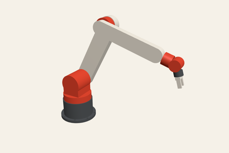
Eight solids on six revolute joints: a 300 mm upper arm, a 250 mm forearm, a roll-and-pitch wrist and a parallel gripper. The kernel finds no overlap between any two parts, and the drawing lists every part.
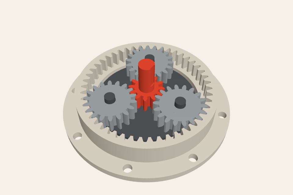
Module 2 involute gears: a 12-tooth sun, three 18-tooth planets on a carrier and a 48-tooth ring in a bolted housing. The gear mesh is checked for interference in the real kernel.
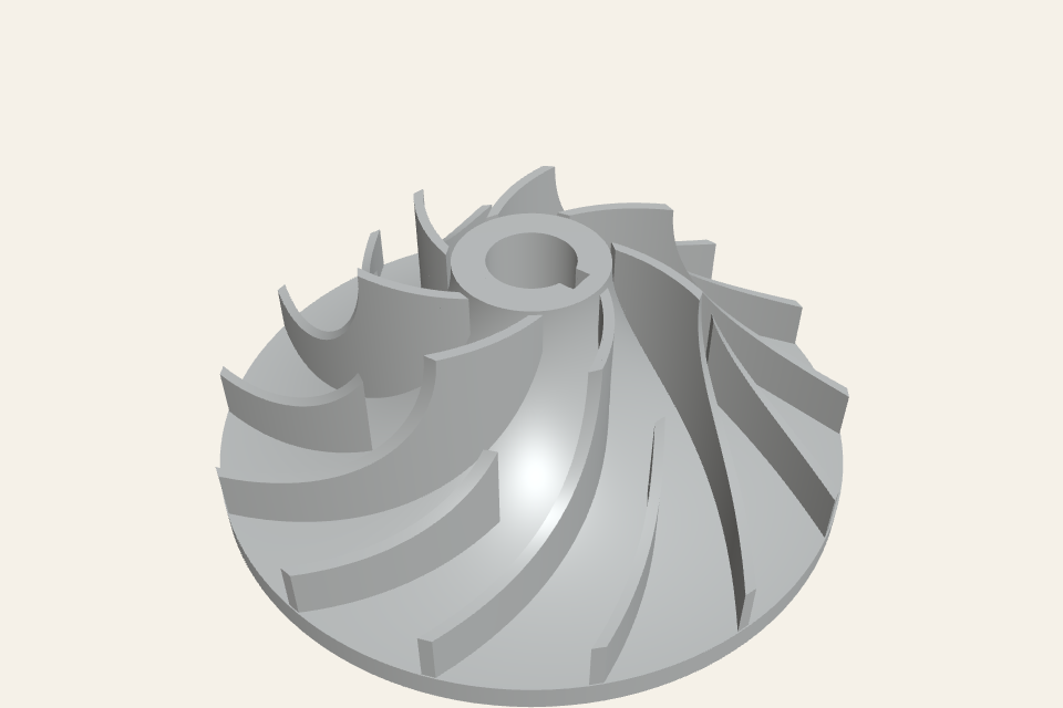
120 mm across, with seven backward-curved blades and seven splitters on one logarithmic spiral and a 16 mm keyed bore. One solid; the STEP is re-imported and compared.
04Like a patient design engineer
When a key dimension is unclear, it asks. When a sensible default exists, it says so and carries on. After each build it captures several views and checks them against your request before handing the result over.
Views it checks after each build
Up to 4 sketches or photos. It first describes what it sees.
Each project keeps a design brief, so many rounds of edits stay on track.
Subscribers switch between light, balanced and deep. Deeper is more thorough and uses more credits.
Continue on another computer with the source, parameters and conversation intact.
05Beyond the first model
Attach up to 4 sketches or photos, or a PDF drawing. The AI CAD generator first describes what it reads, then asks about anything unclear before it models.
Import an existing part as STEP, up to 32 MB. The exact solid stays intact and new features are built on it. Add more STEP files to the same project later.
Generate three views, an isometric view and overall dimensions in first- or third-angle projection, then export PDF, DXF or SVG. Available for mechanical parts.
Check a mechanical part against CNC machining, FDM printing and injection moulding rules. Each rule shows its threshold and sampling limits. It is a review aid, not a guarantee.
Set a density for each part and read its mass. Drawings show the material and mass in the title block.
Keep several sets of parameter values in one project, and check key dimensions against your written requirements before you export.
06Text to CAD, explained
Text to CAD turns a written description into editable geometry. The mechanical-parts engine represents solid faces and edges that engineering tools can measure and modify. An exact cylindrical hole can retain its specified diameter in STEP, but generated geometry still needs checking against your dimensions, fits and manufacturing requirements.
You describe the part. The agent asks about missing key dimensions, then writes model code for one of two engines: Replicad for exact-surface mechanical parts, or OpenSCAD for boolean and mesh forms. The code runs in an isolated worker inside your browser, so the model builds on your own machine. After each build the agent captures several views and compares them with your request. The parameters it exposes become sliders, and changing them rebuilds the model locally without a new AI request.
Name the part and its job, then give the dimensions that matter: overall size, hole diameters and positions, wall thickness and the fasteners it must fit. Mention the process if you know it, because a 3D-printed bracket and a machined bracket need different details. If a dimension is not critical, say so. The agent picks a sensible default and tells you what it chose, so you can change it with one slider.
Makers who want a printable part without learning a CAD package. Engineers who want a first parametric draft of a bracket, flange or housing in minutes, then continue in SolidWorks or Fusion with exact STEP. Product designers who need a dimensioned model to discuss with a supplier, together with drawings and a manufacturing check.
Export exact STEP when the part continues in professional CAD or goes to machining. Export STL or 3MF when it goes straight to a slicer. Use GLB, FBX or SketchUp for presentation, and export the engineering drawing as DXF for 2D CAD. Every export is created in your browser from the current model, so the file always matches what you see.
07Plans
Choose monthly or save 20% with annual billing.
08FAQ
An AI 3D model generator produces a mesh for games, renders or rough prints. Text to CAD produces a parametric solid with real dimensions. You can change a value and rebuild, export exact STEP, make engineering drawings and check the part before manufacturing.
You can start by describing a part and its dimensions in everyday language. Inspect the generated geometry and refine it as needed. CAD knowledge helps when a design becomes more complex.
Yes. Mechanical part projects export exact-surface STEP, so holes, fillets and faces stay true geometry you can select, dimension and modify. Geometry projects export a mesh-based STEP, which other tools open but cannot edit as features.
Yes. Import a STEP file up to 32 MB, or attach a PDF drawing and up to 4 sketches or photos. The agent describes what it reads and asks about anything unclear before it models.
Yes. Open the code view to edit your model source, then apply and preview the changes. You can also adjust the parameters exposed by the model.
Mechanical parts export exact-surface STEP, plus DXF, SketchUp (SKP), FBX, DAE, OBJ, STL, 3MF, GLB, glTF and a PNG of the current view. Geometry projects offer the same formats except glTF, and their STEP is a mesh solid. Every export is created in your browser.
The CAD engines run in an isolated worker in your browser, and every export is created there. Generated code cannot reach the network. Your conversation is sent to a model provider, and projects are saved privately to your account.
Model source, parameters, conversations and model files are saved privately to your account. Your browser keeps a cache and unsynced changes. Wait for cloud save confirmation before switching devices; clearing browser storage can remove unsynced work. AI requests are sent to a model provider.
Check dimensions, fit, material and the requirements of your manufacturing process. Generated geometry is a starting point for review, not a certification of safety or manufacturability.